
Views: 0 Author: Site Editor Publish Time: 2026-05-18 Origin: Site


The structural integrity of any industrial, automotive, or architectural build hinges directly on the quality of its skeletal framework; a single micro-fracture or misaligned joint can compromise the entire payload. Fabricators and project engineers face a constant battle against thermal distortion, joint stress concentration, and metallurgical incompatibility. Choosing the wrong filler material, failing to manage heat input accurately, or ignoring compliance standards leads to catastrophic structural failure, costly rework, and severe legal liability.
Successfully executing a Custom Welding Steel Frame project requires shifting from basic fusion techniques to precision-engineered structural fabrication. This guide breaks down the exact metallurgical assessments, fixturing protocols, and non-destructive testing required to produce reliable, high-load structures. You will learn how to match specific arcs to varied alloys, conquer thermal contraction through advanced fixturing setups, and evaluate load-bearing splices to guarantee maximum dynamic stress distribution.
Process-to-Application Matching: MIG provides high-efficiency output for standard mild steel frames, while TIG is mandatory for specialized alloys like chrome-moly tubing used in dynamic load environments.
Distortion Control is Non-Negotiable: Achieving precision-engineered components requires heavy industrial fixturing, fabricating custom 90-degree reference jigs, and pre-setting joints at 1-2 degrees outward to counter cooling shrinkage.
Dynamic Load Reinforcement: Heavy-duty and automotive frames require specialized stress-distribution techniques, including 45-degree angled splices, stop-drilling for crack mitigation, and fish plate reinforcements to remain compliant and safe.
Metallurgical Verification Prevents Catastrophe: Vintage structural steels require strict pre-weld chemical evaluation (e.g., Carbon Equivalent testing) to avoid hot tearing from sulfur/phosphorus impurities and lamellar tearing from manganese sulfide inclusions.
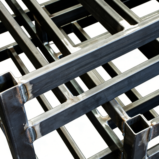
Selecting the correct arc process dictates the total cost of ownership of your fabrication run. It forces operators to balance deposition rates, penetration depths, and requisite skill levels against the mechanical demands of the final structure. Choosing an improper arc method introduces unacceptable risks, ranging from shallow cold laps to uncontrollable burn-through on thin-walled structural tubing. You must evaluate the base metal and environment before locking in a procedure.
For standard mild steel fabrication, Metal Inert Gas (MIG) welding delivers unmatched return on investment. The process provides exceptionally high deposition rates, minimal post-weld slag cleanup, and continuous wire feed operations ideal for high-volume Welded Parts. Operators can lay down extended linear beads rapidly, reducing thermal saturation time across the broader structural assembly. This speed directly translates to lower labor costs per unit on repetitive industrial frames.
Achieving structural certification requires strict adherence to operational parameters. When joining standard 1/8-inch mild steel, operators should follow strict baseline machine parameters to ensure absolute consistency across multiple production lines.
| Material Thickness | Voltage Setting | Wire Feed Speed (IPM) | Shielding Gas Flow |
16 Gauge (0.060") | 15 - 16 Volts | 150 - 170 | 15 - 20 |
1/8 Inch (0.125") | 17 - 19 Volts | 220 - 250 | 15 - 20 |
1/4 Inch (0.250") | 21 - 23 Volts | 320 - 350 | 20 - 25 |
Polarity must remain strictly Direct Current Electrode Positive (DCEP) to maximize root penetration. Consumable matching is equally required. You must pair .030 or .035 diameter solid wire (like ER70S-6) with a 75% Argon and 25% Carbon Dioxide shielding gas mixture. Flow rates must remain locked tightly to completely displace atmospheric oxygen and prevent subsurface porosity.
Tungsten Inert Gas (TIG) welding stands as the undisputed standard for fabricating Precision-engineered components. Unlike automated wire-feed systems, TIG separates the heat source from the filler material. This decoupled action grants operators absolute control over puddle manipulation and heat input, minimizing the heat-affected zone (HAZ) and preventing metallurgical degradation in sensitive base metals.
This process becomes mandatory in high-end automotive applications. Chrome-moly race car frames, roll cages, and aerospace chassis rely entirely on TIG. Attempting to assemble a high-stress chrome-moly chassis with standard MIG processes often results in brittle failure under peak torque. Operators must execute the following prep sequence when TIG welding sensitive aerospace alloys:
Chemically strip the joint surface using industrial acetone to dissolve all surface hydrocarbons.
Sharpen the 2% lanthanated tungsten electrode longitudinally to prevent arc wandering.
Set up a dual-flow regulator to provide internal back-purging with 100% pure Argon, protecting the backside of the root from atmospheric oxidation.
Shielded Metal Arc Welding (SMAW), commonly known as Stick, excels in environments where gas-shielded methods fail. Heavy-equipment frame repairs frequently occur outdoors. High winds strip away inert shielding gases, while decades of rust, grease, and mill scale compromise surface cleanliness. The flux coating on Stick electrodes generates its own protective atmospheric shield while actively pulling impurities out of the molten puddle.
For high-stress structural repairs, E7018 low-hydrogen electrodes play a major role. These specific consumables yield exceptional crack-resistance and superior ductility under dynamic loads. Structural engineers heavily specify E7018 when repairing load-bearing tractor chassis, crane booms, and bridge girders because the resulting bead handles immense flexural strain without shearing.
The geometric layout and chemical composition of your base metal dictate the success of the entire operation. Poor material selection complicates fixturing, while ignoring the metallurgical chemistry of legacy steel guarantees delayed cracking.
When engineering a framework, the choice between square tubing and round tubing heavily influences fabrication velocity. Square tubing dramatically simplifies step-down scaling. Transitioning a structural load path from a 2x2 main rail down to a 1x1 subframe crossmember requires simple, flat-plane alignment. Square tubing allows operators to execute precise 45-degree miter cuts using standard abrasive chop saws. This geometric predictability accelerates fit-up cycles, ensuring tight edge-to-edge contact that minimizes the need for excessive gap-filling filler metal.
Round tubing provides superior torsional rigidity but complicates joinery. Fabricating complex nodes with round tubing requires dedicated tube notchers, precise cope angle calculations, and custom saddle joints. If your facility lacks CNC pipe-profiling equipment, stick to square or rectangular hollow structural sections (HSS) to maximize production efficiency.
Repairing or upcycling vintage steel requires strict engineering oversight. You cannot treat 50-year-old structural beams with the same thermal assumptions as modern, cleanly rolled mild steel. Implementing mandatory Carbon Equivalent (CE) testing represents the first line of defense against catastrophic joint failure.
Legacy steel frequently contains high levels of sulfur or phosphorus impurities, often exceeding 0.05%. These elevated impurity thresholds create extreme risks for "hot tearing" during the rapid cooling phase of the weld pool. Additionally, early manufacturing methods often left legacy manganese sulfide inclusions trapped within the grain structure. When these older steels experience through-thickness tensile stress from a new weld, they become highly susceptible to lamellar tearing.
Mitigation strategies rely directly on calculating the CE value. Engineers utilize specific chemical formulas derived from lab analysis to determine hardenability. If the chemical analysis reveals a CE exceeding 0.4%, operators must implement mandatory preheating protocols. Applying localized heat before striking an arc slows the subsequent cooling rate, preventing the formation of brittle martensite in the HAZ. Welders must strictly utilize low heat input strategies, deploying narrow stringer beads rather than wide weaves to limit thermal shock to the aging base material.
Flawless arc execution cannot overcome poor mechanical preparation. Establish a non-negotiable baseline for shop floor cleanliness. Operators must strictly follow these fit-up standards before initiating any structural joints:
Mechanically clean all joint surfaces using heavy wire wheels or abrasive flap discs. Extend this cleaning at least 1-2 inches outward from the intended weld zone to aggressively strip away mill scale, industrial oils, and oxidation.
Bevel or chamfer the mating edges on all thick frame components to ensure the arc penetrates fully down to the root face.
Enforce a strict 1/16-inch root gap for standard horizontal butt joints. This gap allows the molten filler to bridge the entire thickness of the material rather than pooling superficially on top.
Utilize overlapping lap joints instead of simple butt joints wherever possible to exponentially maximize the load-bearing surface area.
Metal inevitably shrinks toward the heat source during the cooling cycle. This localized contraction pulls rigid members out of square, warping the assembly and destroying the dimensional accuracy of engineered Metal components. Overcoming this physical law requires strategic foresight, robust clamping infrastructure, and disciplined sequencing.
Factory-level production relies on massive, rigid fixturing platforms. Heavy clamping systems physically restrain the frame layout throughout the entire thermal cycle, forcing the metal to yield internally rather than distorting externally. On the standard shop floor, fabricators can replicate this restraint by building custom 90-degree angle-iron triangles. These reusable, highly rigid reference jigs lock corners into perfect perpendicular alignment before the operator ever drops their hood.
The most effective countermeasure is the "pre-set allowance" technique. Rather than forcing a joint into a perfect 90-degree angle before tacking, experienced fabricators intentionally lean the joint angles 1-2 degrees outward. As the massive heat of the puddle dissipates, the natural cooling contraction pulls the perpendicular member exactly back to a true, square 90 degrees. This requires practice and familiarity with specific alloy contraction rates.
Continuous, end-to-end welding destroys frames. Applying uninterrupted heat along a single seam introduces massive, localized thermal expansion. You must implement a strict procedural framework to combat this. Begin by utilizing aggressive tack welding on all external edges and corners. After securing the tacks, measure the frame diagonally from corner to corner to verify absolute squareness.
Once verified, alternate your weld locations using the 4-point stagger method. Weld a two-inch segment on the front left quadrant, then immediately move to the rear right quadrant. This staggered sequencing strategy forces the thermal load to distribute evenly across the entire spatial footprint of the chassis, neutralizing localized pulling forces and retaining structural geometry.
Sometimes the most advanced Welding processes involve knowing when not to weld. For immense frameworks requiring extreme dimensional accuracy or frequent field adjustments, full continuous seams introduce unacceptable distortion risks. Instead, integrate a hybrid methodology. Fabricators should utilize heavy welded brackets, precision bolt sleeves, high-grade locknuts, and metal shims. This modular approach eliminates long continuous thermal cycles, prevents warping, and allows technicians to fine-tune alignments dynamically during final assembly.
Frame rails face constant flexural strain and torsion. Splicing a severed or extended load-bearing horizontal frame rail requires geometric planning. You must completely rule out the use of a simple, straight vertical butt joint. A vertical seam perpendicular to the load path creates an immediate, localized stress riser. When the frame flexes, the entire mechanical load concentrates directly on that narrow cross-section, guaranteeing eventual fatigue failure.
Instead, heavily advocate for the 45-degree angled cut and splice. Diagonal slicing elongates the joint, dramatically maximizing the available surface area for filler metal. The angled geometry forces dynamic load stresses to distribute smoothly across a much wider lateral plane, eliminating the sharp stress concentration found in vertical cuts.
Standard fabrication rules change immediately when scaling up to commercial vehicles, working with specialized environmental alloys, or assessing irreversible structural damage. Operating on a Welding Steel Frame requires strict adherence to industry-specific legal and chemical mandates.
Repairing cracked truck frames falls under intense scrutiny from the Department of Transportation (DOT). You cannot simply drag a hot bead across a chassis crack and send the vehicle back onto the highway. Repairing dynamic load fractures requires the "stop-drill" method.
Locate the absolute micro-terminus of the fracture using dye penetrant.
Drill a small, clean hole at the exact end point of the crack. This circular void halts linear propagation, preventing it from creeping further down the rail during the thermal shock of repair.
Gouge the crack out to a V-groove to ensure 100% root penetration.
Weld the defect using E7018 or dual-shield flux core wire.
Grind the surface flush.
Following the root repair, structural reinforcement becomes a legal and physical necessity. Fabricators must install heavy steel fish plates or sleeve plates over the repaired zone. When securing these reinforcement plates, utilize "stagger welds" rather than laying a continuous bead around the entire perimeter. Intermittent staggered beads prevent the parent frame rail from overheating, annealing, and subsequently weakening at the edges of the reinforcement plate.
Architectural installations and outdoor industrial frames frequently utilize weathering steel, commonly specified under ASTM A588 or the brand name Cor-Ten. This specialized metallurgical alloy features distinct ratios of copper, chromium, and nickel. When exposed to cyclical wet and dry weather, the steel oxidizes to form a dense, self-healing copper-rust patina that protects the internal iron from structural degradation.
This protective patina presents a critical failure point during fabrication. You must aggressively grind the surface rust down to bright, bare metal before striking an arc. Failing to remove the patina forces dense oxides directly into the weld pool, causing severe porosity and immediate structural failure.
Selecting the correct filler metal matrix for Corten depends on the joint design. For single-pass welds, operators can utilize standard AWS E7018 or ER70S consumables. The deep penetration of a single pass dilutes the base metal directly into the puddle, infusing the bead with enough native copper and chromium to provide matched corrosion resistance. Multi-pass welds isolate the upper cover passes from the base metal entirely. For thick joints, you must mandate specialized low-alloy fillers, such as Cor-Match, to guarantee structural integrity, color matching, and long-term atmospheric resistance.
Safety and economics eventually intersect. Fabricators must establish objective criteria for determining when a repair becomes mathematically and legally unviable. Severe, multi-point rust degradation that thins the wall thickness below acceptable tolerances cannot be patched safely. Likewise, frame rails exhibiting compound bends across primary load-bearing zones suffer from permanent plastic deformation. Attempting to heat, bend, and weld these compromised structures creates severe liability. Complete frame replacement provides the only safe return on investment.
Assuming a framework is safe based solely on visual appearance invites disaster. Industrial evaluation frameworks require multi-tiered inspection methodologies to guarantee safety and performance across heavy-duty steel structures.
Visual inspection serves as the first line of defense on the shop floor. Operators must understand how surface defects indicate deeper operational failures. The table below outlines critical surface anomalies, their root causes, and the necessary corrective actions.
Visual Defect | Root Cause Indicator | Corrective Action / Solution |
Porosity (Surface Holes) | Signals gas coverage failure, drafts, or dirty base metal. | Verify gas flow at 15-20 CFH. Clean mill scale and oils thoroughly. |
High/Narrow Beads | Signals travel speed is too slow or voltage is too low. | Increase travel speed. Adjust voltage upward to flatten the puddle. |
Excessive Spatter | Signals voltage is set too high or wire feed speed is mismatched. | Reduce voltage settings. Check for erratic wire feed tension. |
Undercutting | Signals poor gun angle or excessively fast travel speed. | Slow travel speed. Pause briefly at the toes to allow filler accumulation. |
Surface evaluation cannot detect internal flaws. Critical infrastructure requires heavy reliance on industrial Non-Destructive Testing (NDT). Ultrasonic testing (UT) utilizes high-frequency sound waves to map the internal density of the joint, instantly detecting subsurface cold lapping, lack of side-wall fusion, or hidden internal porosity. Similarly, X-Ray radiography provides a permanent visual record of the internal grain structure.
When working with sensitive alloys and low-hydrogen electrodes, engineers enforce the strict hydrogen-delay rule. Hydrogen atoms introduced during the thermal cycle can migrate through the crystalline structure, accumulating in stress pockets and causing delayed microscopic fractures. To accurately detect this phenomenon, inspectors must delay all NDT evaluations for a minimum of 48 hours post-weld to ensure delayed cold cracking has not materialized.
Theoretical engineering requires physical validation. Mandate physical load testing alongside precise post-weld dimensional measurements. Applying calculated hydraulic stress to the fabricated frame ensures the finished component handles real-world dynamic forces without catastrophic yielding.
Building or repairing a high-load skeletal framework requires treating the project as a strict metallurgical engineering task. Execute these immediate next steps to ensure structural integrity and compliance on your upcoming fabrication projects:
Standardize and document your shop's Welding Procedure Specifications (WPS) to ensure repeatable voltage and gas parameters across all operators.
Fabricate dedicated 90-degree heavy-steel clamping jigs before initiating layout, using them strictly as non-negotiable reference points for all structural corners.
Implement mandatory training for all operators on dynamic stress-distribution techniques, ensuring they master fish-plating, stagger-welding, and stop-drilling procedures.
Enforce a strict 48-hour quarantine on all critical high-stress repairs utilizing low-hydrogen electrodes before scheduling any ultrasonic or radiographic NDT inspections.
A: Set your machine to 17-19 Volts with a wire speed of 3-4. You must use .030 or .035 solid wire, maintain DCEP polarity, and utilize a 75/25 Argon/CO2 shielding gas mixture. Keep gas flow rates steadily between 15-20 CFH to displace oxygen and prevent internal porosity completely.
A: Secure the assembly using heavy fixturing blocks and custom 90-degree angle iron jigs. Sequence your tack welds diagonally from corner to corner to distribute heat evenly. Most importantly, pre-set your joints 1-2 degrees outward to mathematically account for the inward pull of thermal cooling contraction.
A: For standard horizontal butt joints, always maintain a strict 1/16-inch root gap. This space guarantees proper thermal penetration entirely through the root thickness of the base metal. You must also aggressively clean the material 1-2 inches back from the joint edges before beginning fit-up.
A: Yes, provided you strictly follow DOT compliance guidelines. You must drill crack-stopping holes at the terminal ends of any fractures to halt propagation. Employ high-strength E7018 electrodes and install heavy steel fish plates using staggered welds to distribute dynamic load stress safely across the rail.
A: Yes. You must grind the pre-existing copper-rust patina entirely down to bright bare metal before striking an arc. Single-pass welds can use standard ER70S fillers, but thick, multi-pass joints demand specialized matching low-alloy fillers like Cor-Match to retain the long-term atmospheric resistance of the material.
A: A straight vertical cut completely perpendicular to the rail creates an immediate stress riser, concentrating flexural load directly onto a single cross-section. Splicing rails at a 45-degree angle dramatically increases the weld surface area and distributes dynamic stress across a much wider lateral structural plane.
A: For critical applications utilizing low-hydrogen electrodes, rigorous industrial standards mandate waiting at least 48 hours post-weld. This delay ensures migrating hydrogen atoms have adequate time to manifest into delayed microscopic cold cracking before you conduct final internal Ultrasonic or X-Ray radiographic non-destructive testing.


